
Technical Guide to MBBR Suspended Carrier Selection and Application
Technical Guide to MBBR Suspended Carrier Selection and Application
Article Directory
-
What is a Moving Bed Biofilm Reactor?
-
Core Components of an MBBR Reactor
-
Core of MBBR Technology: MBBR Suspended Carrier Specifications and Selection
-
Key Advantages of MBBR Technology
-
Core Design Parameter Specifications for MBBR Reactors
-
Core Equipment Selection Specifications for MBBR Systems
-
Core Application Scenarios for MBBR Technology and MBBR Carriers
-
Direct Supply from an MBBR Carrier Manufacturer
1. What is a Moving Bed Biofilm Reactor?
The Moving Bed Biofilm Reactor, commonly known as the MBBR process, is also frequently referred to within the industry as the suspended carrier process. It is a high-efficiency wastewater treatment technology that integrates the advantages of suspended growth activated sludge and attached growth biofilm processes. With core characteristics of simplicity, stability, operational flexibility, compact structure, and low operating and maintenance costs, it has become one of the mainstream mature technologies in the global wastewater treatment sector.
Different configurations of MBBR reactors can stably achieve full-process treatment for carbon removal, nitrification, and denitrification, meeting the most stringent domestic effluent standards for nitrogen and phosphorus removal. They are widely applicable to high-concentration organic wastewater treatment in industries such as chemicals, slaughtering, food processing, pharmaceuticals, biological fermentation, textile printing and dyeing, as well as municipal domestic sewage treatment, and upgrading and expansion projects for existing municipal and industrial wastewater treatment plants.
The core operating principle of the MBBR process involves adding specialized MBBR suspended carriers to the reactor. Using aeration agitation, liquid recirculation, or mechanical mixing, the carriers are fluidized uniformly within the reactor. A highly specific active biofilm gradually grows on the carrier surface, efficiently degrading various pollutants in the wastewater through microbial metabolism. A dedicated retention device is installed at the reactor outlet to stably retain the MBBR carriers within the reactor, ensuring continuous and stable operation of the treatment system. Under normal operating conditions, the filling ratio of MBBR carriers in the reactor is 30% to 60% of the reactor volume.
As a professional source manufacturer and supplier of MBBR carriers and suspended carriers, Xiaolaoban specializes in providing a full range of MBBR suspended carrier products suitable for different processes and water quality scenarios, supporting customized production to fully meet the design and operational requirements of various MBBR reactors.
2. Core Components of an MBBR Reactor
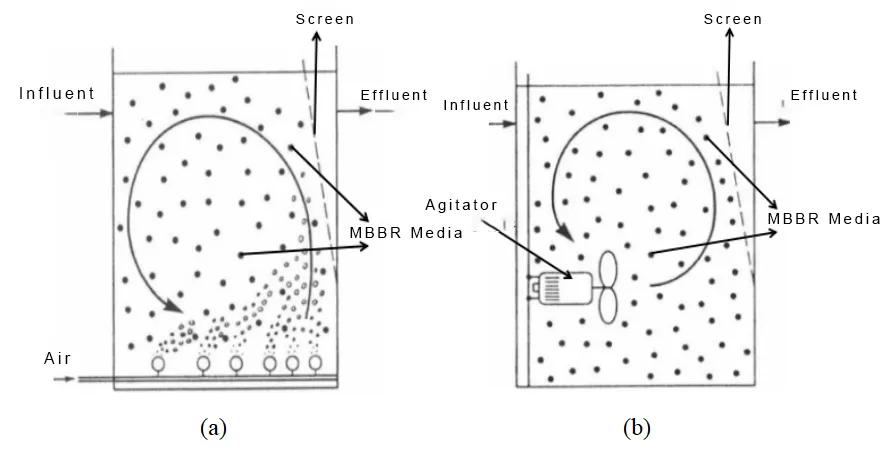
MBBR processes are primarily classified into two types based on operating conditions: aerobic MBBR and anoxic MBBR. The core components of an aerobic MBBR tank consist of the tank body, suspended carriers (MBBR carriers), aeration system, and outlet screen. The anoxic MBBR tank differs from the aerobic configuration by not having an aeration system; instead, it is equipped with a dedicated mixer to achieve carrier fluidization and mixing.
2.1 Tank Body
The MBBR reactor tank body can be flexibly designed in circular or rectangular shapes based on project site and treatment scale. Aerobic MBBR tanks utilize bottom aeration to provide the primary power for carrier fluidization. Anoxic MBBR tanks achieve uniform mixing of wastewater and carriers within the tank by installing dedicated submersible mixers. The two core configurations are illustrated in the diagram. Figure 1: Schematic diagram of MBBR reactor configurations (a: aerobic MBBR; b: anoxic MBBR)
2.2 Outlet Retention Screen
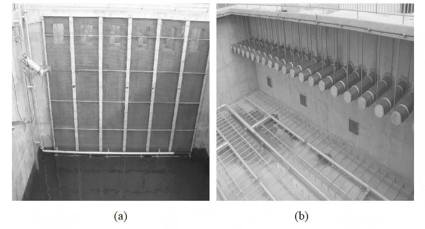
Commonly used outlet screens for MBBR reactors fall into two main types: vertically fixed stainless steel flat screens and horizontally placed wedge wire stainless steel screens. To prevent the accumulation and blockage of carriers and debris at the screen, an air jet device or mixer must be installed at the bottom of the screen. This ensures smooth effluent flow and fundamentally prevents the loss of MBBR carriers with the effluent. Figure 2: Examples of retention screens (a: vertical flat screen with air jet system; b: horizontal wedge wire stainless steel screen)
3. Core of MBBR Technology: MBBR Suspended Carrier Specifications and Selection
The suspended carrier is the core component of the MBBR process. The carrier's specific surface area, material, fluidization performance, and aging resistance directly determine the reactor's treatment efficiency, operational stability, and system energy consumption. This is a critical step in the design of all wastewater treatment projects and equipment selection.
3.1 Core Performance Requirements for MBBR Carriers
High-quality MBBR suspended carriers must possess core characteristics such as a large specific surface area, strong corrosion and aging resistance, precise density, good fluidization performance, and fast biofilm formation. Currently, mainstream MBBR carriers are mostly made from materials like polyethylene, polypropylene and their modified materials, and polyurethane foam. The density is precisely controlled between 0.95 and 0.98 g/cm³, slightly lower than water, allowing for uniform fluidization throughout the tank under low energy conditions without the need for backwashing, significantly reducing operational energy consumption and daily maintenance costs.
3.2 Specifications of Mainstream MBBR Suspended Carriers
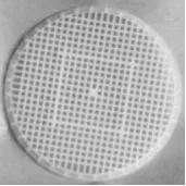
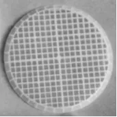
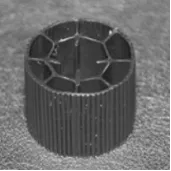
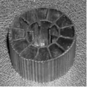
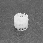
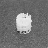
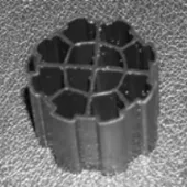
The commonly used MBBR carriers in domestic wastewater treatment projects are primarily K-type carriers and their optimized variants. The core specifications are shown in the table below. As a professional suspended carrier supplier, Xiaolaoban can provide all series of products listed in the table, as well as custom-made MBBR carriers based on project water quality and process requirements.
Table: MBBR Carrier Specifications
| Specific Surface Area (m²/m³) | Nominal Size (mm) (Height; Diameter) | |
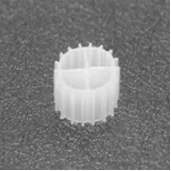 |
500 | 7 ; 9 |
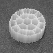 |
500 | 12 ; 25 |
 |
1200 | 2 ; 48 |
 |
900 | 2 ; 48 |
 |
450 | 15 ; 22 |
 |
515 | 15 ; 22 |
 |
600 | 14 ; 14 |
 |
660 | 12 ; 12 |
 |
589 | 14 ; 18 |
4. Key Advantages of MBBR Technology
-
High Treatment Efficiency and Strong Shock Load Resistance: The MBBR process can form highly specific active biofilms on the carrier surface, significantly improving the pollutant treatment efficiency per unit volume of the reactor. It simultaneously enhances process stability, effectively handling large fluctuations in water quality and flow rate, while reducing the reactor footprint and lowering project civil construction costs.
-
Simple Operation and Maintenance, No Backwashing Required: Unlike traditional biofilm processes, MBBR does not require periodic backwashing of the carriers. This significantly reduces head loss and operational complexity, lowering manual maintenance costs and operational difficulty, making it suitable for long-term stable operation.
-
Operational Flexibility, Adaptable to Multi-Scenario Treatment Needs: Multiple reaction zones can be arranged sequentially along the water flow direction to simultaneously achieve various treatment objectives such as carbon removal, nitrification, pre-/post-denitrification, meeting diverse water quality requirements like nitrogen and phosphorus removal in a single system without major structural adjustments.
-
Strong Adaptability, Low Upgrade and Retrofit Cost: It can be directly adapted to existing tank structures in wastewater treatment plants for upgrades without extensive civil construction. This enables rapid plant capacity expansion and effluent quality improvement, significantly reducing the cost and construction period of upgrades, making it a preferred technology for plant retrofitting.
5. Core Design Parameter Specifications for MBBR Reactors
The number or compartments of MBBR reactors should be no less than two, designed for simultaneous operation. Core design parameters refer to national standards such as the "Water Supply and Drainage Design Manual" and mature engineering practices, as detailed below. These provide authoritative references for project design and MBBR carrier selection:
-
The required carrier volume is calculated based on the carrier volumetric loading rate and the average daily wastewater flow rate. The volumetric loading rate should preferably be determined through experimentation. In the absence of experimental data, for projects primarily treating domestic/municipal wastewater, the recommended typical volumetric loading rate for the MBBR process is 1.0–1.4 kg BOD₅/(m³·d).
-
For MBBR systems primarily aimed at carbon removal, the recommended Surface Area Loading Rate (SALR) for BOD is as follows: High-load conditions (75%–80% BOD removal) > 20 g/(m²·d); Conventional-load conditions (80%–90% BOD removal) 5–15 g/(m²·d); Low-load conditions (pre-nitrification) ≤ 5 g/(m²·d).
Table: BOD Surface Area Loading Rate (SALR)
| Application Purpose | BOD Surface Area Loading Rate (SALR) [g/(m²·d)] |
| High Load (75%–80% BOD removal) | > 20 |
| Conventional Load (80%–90% BOD removal) | 5–15 |
| Low Load (pre‑nitrification) | ≤ 5 |
-
Design parameters for denitrification conditions: The recommended pre-denitrification rate is 0.15–1.0 g/(m²·d). For post-denitrification with excess external carbon source, the maximum nitrate removal rate per carrier surface area can exceed 2 g/(m²·d).
-
The specific surface area of MBBR carriers is typically selected within the range of 200–600 m²/m³, chosen flexibly based on treatment goals and influent loading.
-
The carrier filling ratio is generally controlled between 30% and 60%, determined by the process flow and influent/effluent water quality. Higher loading rates correspond to higher required filling ratios.
-
Peak Velocity Design: The horizontal flow velocity in the reactor under peak flow conditions must be checked. When the horizontal velocity is < 20 m/h, carriers are uniformly distributed within the reactor. When the horizontal velocity exceeds 35 m/h, issues like carrier accumulation and sudden head loss increases are prone to occur. Peak hydraulic conditions directly determine the reactor's geometry and the number of series.
-
Reactor Length-to-Width Ratio Design: A length-to-width ratio < 1:1 effectively reduces carrier migration towards the retention screen under peak flow conditions, ensuring uniform distribution within the tank.
-
Hydraulic Retention Time (HRT): Recommended HRT for anoxic MBBR is 1.0–1.2 hours; for aerobic MBBR, it is 3.5–4.5 hours. The dissolved oxygen concentration in the aerobic tank should be controlled between 2.0–6.0 mg/L.
-
The recommended surface loading rate for the accompanying secondary clarifier is 0.5–0.8 m³/(m²·h).
6. Core Equipment Selection Specifications for MBBR Systems
6.1 Pretreatment Unit
Inert materials such as scum, plastics, and sand/grit are difficult to remove once they enter the MBBR reactor and can easily cause system clogging, carrier abrasion, and shorten the carrier lifespan. Therefore, adequate pretreatment systems are mandatory for MBBR influent.
Standard conditions require properly designed screens and grit chambers. For projects with a primary treatment unit, the screen opening should be ≤ 6 mm. For projects without a primary treatment unit, fine screens with openings of 3 mm or less must be installed.
For existing process upgrade projects, if the existing pretreatment level meets the specified requirements, no additional screens are necessary.
6.2 Aeration System
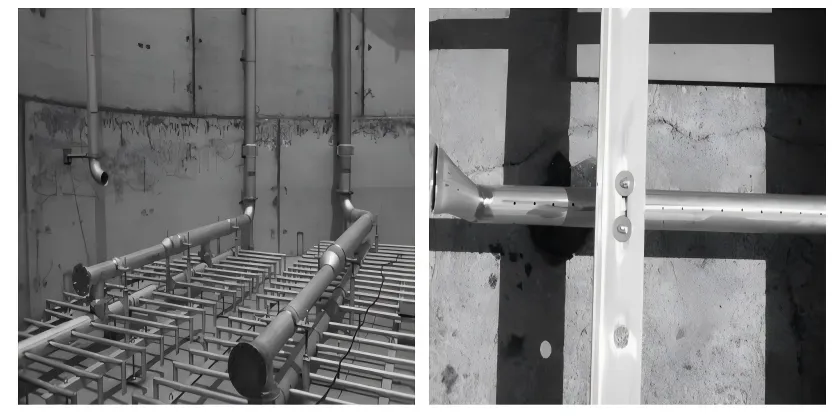
Aerobic MBBR processes typically utilize custom-designed perforated pipe aeration systems. The aeration grid consists of air distribution pipes and small-diameter diffusers with 4 mm aeration holes at the bottom. The coarse bubble aeration mode, combined with stainless steel material and high-strength structural design, ensures that the aeration system requires no daily maintenance and no periodic replacement of diffuser components, significantly reducing system operating and maintenance costs. Figure 3: Example of a perforated aeration system
6.3 Mixer
For denitrification anoxic MBBR reactors, submersible mixers are required to achieve carrier circulation and uniform mixing. The core specifications for mixer selection and installation are as follows:
-
Installation Requirements: The mixer should be positioned close to the water surface, avoiding placement too deep to prevent air entrainment which could affect denitrification. It should be tilted slightly downward to push carriers to the deeper parts of the reactor, ensuring uniform fluidization throughout the tank.
-
Power Configuration: For non-aerated MBBR reactors, a mixing power of 25–35 W/m³ should be provided to ensure effective agitation of the carriers throughout the tank.
-
Filling Ratio Compatibility: Mixing efficiency is higher under low carrier filling ratios, while high filling ratios can lead to poor carrier circulation. The combination of a low filling ratio and a high carrier surface loading rate can increase biofilm concentration, improve carrier settling characteristics, and facilitate more uniform fluidization.
7. Core Application Scenarios for MBBR Technology and MBBR Carriers
Leveraging its core advantages of high efficiency, stability, flexibility, and low operating and maintenance costs, MBBR technology and its MBBR suspended carriers are widely used in the following wastewater treatment scenarios:
-
New construction projects for municipal domestic sewage treatment plants, as well as upgrading and expansion projects for existing plants.
-
High-concentration organic wastewater treatment: industrial wastewater from sectors such as chemicals, pharmaceuticals, biological fermentation, textile printing and dyeing, food processing, slaughtering, and aquaculture.
-
Decentralized rural wastewater treatment, new construction and renovation projects for township sewage treatment stations.
-
Treatment of challenging wastewater, such as landfill leachate, coal chemical wastewater, and hospital wastewater.
8. Direct Supply from an MBBR Carrier Manufacturer
SmallBoss is a professional source manufacturer and supplier of MBBR carriers and suspended carriers. With years of dedicated experience in the R&D and production of wastewater treatment carriers, the company possesses fully automated production lines and a comprehensive product testing system. We can supply all series of MBBR suspended carrier products detailed in this document, as well as provide customized carrier production and one-on-one technical selection services based on project water quality and process design requirements.
Our MBBR carrier products feature core advantages such as high specific surface area, good fluidization performance, aging and corrosion resistance, fast biofilm formation, high treatment efficiency, and long service life. They have been widely used in various municipal and industrial wastewater treatment projects across the country, providing a one-stop MBBR carrier solution for your wastewater treatment needs.
For detailed parameters, product quotations, or customized services for MBBR carriers, please feel free to contact us. We offer free technical support and selection solutions.
References
[1] Beijing General Municipal Engineering Design & Research Institute. Water Supply and Drainage Design Manual. Volume 5, Urban Drainage [M]. China Architecture & Building Press, 2017.


